March 2, 2026
Container Data Center: What a "Data Center in a Container" Really Means (and What to Specify)
Practical spec guide for containerized data centers: mechanical/electrical interfaces, transport limits, commissioning tests, monitoring integration (SNMP/Redfish/Modbus), and security baseline controls.
If you've been asked to specify or procure a "container data center," you've already run into the problem: the term means at least four different things depending on who's selling it.
An ISO 20-foot module with 4 racks and 14 kW of IT load. A wide-body prefab enclosure running 150 kW/rack AI inference. A multi-module system where IT, power, and cooling live in separate containers. A vendor portfolio name covering everything from a small telecom edge unit to a full campus module.
Each of these ships, installs, and commissions differently. Each one has different mechanical, electrical, and controls interfaces at the site boundary. And each one will cause a different set of surprises if the procurement spec treats them as the same product.
This guide cuts through that. It's written for system integrators and infrastructure engineers who need to specify a data center in a container correctly — not conceptually, but in enough detail to drive a responsible procurement, manage a handover, and reduce redesign risk during fabrication and commissioning.
We cover form factor taxonomy, a detailed specification checklist covering all six interface categories, transport constraints for EU and MENA deployments, an acceptance testing framework, a monitoring integration blueprint, and a security baseline. Standards references are included where they anchor enforceable contract language.
What "Container Data Center" Actually Refers To: A Taxonomy That Matters
Before you write a single spec line, you need to know which form factor you're actually buying. The mechanical interface, transport method, and on-site hookup scope all flow from this decision.
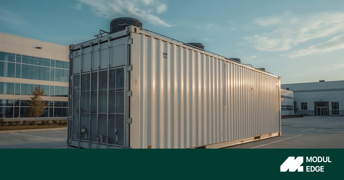
Form Factor 1: ISO Freight Container Module (20 ft / 40 ft, often High Cube)
These modules use Series 1 freight container dimensional classes and corner fittings intended for intercontinental container traffic. The ISO 20' High Cube reference envelope is approximately 6,058 mm × 2,438 mm × 2,896 mm. ISO container geometry simplifies intermodal handling but does not guarantee last-mile road compliance — height, weight, and route permits still apply.
This is the most widely understood form factor and the easiest to price for logistics. It is not always the best fit for high-density workloads or multi-rack deployments.
Form Factor 2: Custom (Non-ISO) Wide-Body Enclosure
Modules wider than 2,438 mm — for example, 3,495 mm — are built to fit more racks per module or to integrate hot/cold aisle containment without sacrificing usable floor area. They move via specialized heavy transport, require route surveys, and typically need crane plans that differ from ISO container handling. Every dimension above ISO envelope increases permitting complexity, especially for the EU's regulated road freight corridors.
Form Factor 3: Multi-Module System (IT + Power + Auxiliary)
Some architectures deliberately separate the IT module from the power module (transformer, UPS, switchgear) and from auxiliary modules (NOC, spares, monitoring). This changes the procurement scope significantly: the "data center boundary" is now a module network, not a single container boundary. The electrical and controls interfaces between modules must be explicitly specified — they don't come standard.
Form Factor 4: Vendor Portfolio Term
"Modular data center" and "prefabricated modular data center" are frequently marketing terms for a product range, not a specific product. When a vendor uses these terms, always ask: what is the exact module type, what is the transport form factor, and what is the complete interface set for this specific configuration? Spec writers must pin these items into the procurement schedule before pricing or engineering begins.
The practical rule: reliability tier, cooling topology, and redundancy class are orthogonal to the container form factor. A transportable module can be designed to meet Tier III principles or run as a simple N+1 system — the form factor alone tells you nothing about availability. Always specify topology and performance separately from envelope.
The Specification Checklist: Six Interface Categories You Must Nail Before Fabrication
The container module is a boundary object. Your specification job is to define exactly what crosses that boundary and what doesn't — mechanically, electrically, thermally, in controls, in fire/safety, and in security. Miss one category, and you'll be negotiating scope mid-build.
1. Mechanical Interface: Dimensions, Weight, Lifting, and Floor Loading
Minimum to specify:
- External L × W × H, including door swing and required service clearances on all sides
- Internal usable envelope (rack bay count, row spacing, aisle width)
- Tare weight, operating mass, and shipping mass with center of gravity coordinates
- Certified lifting points and allowable lift method (ISO corner fittings vs. custom padeyes vs. spreader bar)
- Tie-down point locations and allowable lashing forces
- Floor build-up (raised floor vs. slab), allowable static and rolling loads for racks and UPS batteries, and anchorage method
Choice points that change the interface:
- ISO corner-casting handling vs. custom lifting lugs (affects crane and rigging plan)
- Raised floor vs. slab (affects airflow management, cable routing, and floor load distribution)
- Seismic zone (if applicable, changes anchorage design and structural spec)
- Battery chemistry and mass (lithium vs. VRLA drives weight planning)
What good looks like: A fabricator submittal that includes a dimensioned drawing with door positions, a center-of-gravity table, a lashing/rigging attachment point map, and allowable rack bay loads per floor zone. If the vendor can't produce these, you're buying an unspecified enclosure.
2. Electrical Interface: Input, Redundancy, Grounding, and PDUs
Minimum to specify:
- Input power mode: commonly 380/400/415 V, 50/60 Hz, three-phase four-wire + PE
- Permitted input voltage range and power factor
- Incoming protection: main breaker rating, discrimination/coordination requirements, labeling
- Grounding interface: single external bonding point, internal equipotential bonding, earthing conductor sizing, neutral-ground scheme (TN-S vs. IT vs. TT, jurisdiction-dependent)
- UPS topology: N, N+1, or 2N — stated explicitly, not implied
- Cooling and distribution redundancy declared using the same notation (N, N+1, 2N)
- Rack PDU type: metered vs. switched, outlet mix, ratings, and whether busway or discrete PDU
- Cable entry: entry side, gland plate sizes, permitted cable diameters, power/fiber segregation requirements
Choice points that change the interface:
- LV intake vs. medium-voltage intake with integrated transformer (changes site electrical works significantly)
- Single utility feed vs. A/B dual feeds to independent UPS paths (changes generator, ATS, and switchgear scope)
- Rack PDU vs. busway (changes monitoring granularity and distribution architecture)
- Isolated ground scheme for sensitive loads (adds earthing design requirement)
Standards anchors: IEEE grounding recommended practices and applicable electrical installation codes define safe grounding interface requirements. If targeting Tier III-style concurrent maintainability, performance confirmation tests under failure scenarios must be written into the spec — not assumed from topology.
3. Thermal Interface: Cooling Topology and Connections
Minimum to specify:
- Cooling topology: DX (direct expansion), chilled water, adiabatic, or integrated close-coupled cooling — stated as a hard choice, not a range
- External heat rejection: is the chiller/dry cooler site-provided or included in the module? Who owns the connection, isolation valves, and instrumentation on the customer side?
- If chilled water: supply/return connection size and type, design ΔT, design flow rate, condensate drain provision, glycol compatibility
- If DX: refrigerant type, line set routing and maximum length, condensing unit location
- External ambient operating range and altitude (cooling unit derating applies at altitude)
- Internal target conditions: rack inlet temperature and humidity targets, in line with "recommended" thermal envelopes from ASHRAE guidelines (the allowable envelope is not the design target — it is the functional operation limit)
Choice points that change the interface:
- DX vs. chilled water vs. liquid cooling (completely different site civil and MEP works)
- Single CW loop vs. dual redundant loops (changes pipe count, valving, and controls)
- Hot-aisle containment or cold-aisle containment (affects rack layout, airflow direction spec, and cooling unit placement)
- Free cooling mode (requires controls logic, weather data, and seasonal setpoint management)
For deployments in MENA or Central Asian climates, free cooling — using ambient air or adiabatic pre-cooling — can deliver meaningful energy efficiency gains during cooler months. Specifying this requires both a controls interface (outdoor temperature sensor, economizer mode logic) and an explicit weather file for the site.
What good looks like: A thermal interface drawing showing connection locations, isolation valve responsibility, and instrumentation that the site must provide, plus a cooling unit derating table by ambient temperature.
4. Fire Protection and Safety Interlocks
Minimum to specify:
- Detection method: conventional smoke, addressable point detection, or aspirating smoke detection (ASD)
- Suppression agent: clean agent (specify agent type) or alternative
- EPO (Emergency Power Off) interlock logic and manual override locations
- Suppression discharge interlock with HVAC shutdown and access control
- Fire panel alarm routing to monitoring gateway (syslog or protocol event output)
- Local audible/visual warning devices
Choice points that change the interface:
- Multi-zone release vs. single-zone (changes agent quantity and detection complexity)
- ASD sensitivity levels (aspirating systems have different commissioning scope than point detection)
- Local code jurisdiction — clean agent system design requirements and discharge policies vary across EU, GCC, and Central Asian markets
Standards anchors: NFPA 75 covers fire protection requirements for IT equipment areas; NFPA 2001 covers clean agent extinguishing systems. Where local codes diverge, identify the applicable authority having jurisdiction early — not during commissioning.
5. Monitoring and Controls Interface
Minimum to specify:
- Protocol stack: SNMP (specify v3), Redfish (HTTPS/REST), Modbus TCP/RTU, or a combination
- Gateway location: is the monitoring gateway inside the module or site-provided?
- Data ownership and local retention: how many days of local telemetry are retained before export?
- Out-of-band management network path: physically separated from production network, with ACLs defined
- Modbus register map: this is vendor-specific by definition — it must be delivered as a contractual document, not assumed
- Integration targets: which systems does the module's gateway connect to? NMS, DCIM, SCADA, SOC/SIEM?
Minimum telemetry point list (contractual regardless of protocol):
- Power chain: utility input status, UPS mode, battery state-of-charge and remaining time, bypass status, output load %, rack PDU branch load, ATS position
- Thermal: cold-aisle or rack-inlet temperature, humidity, cooling unit status, fan status, setpoints, alarms; if chilled water, supply/return temperature and flow
- Safety: fire system trouble/alarm state, suppression armed status, EPO status, smoke detector state
- Physical security: door open/closed events, access granted/denied events, CCTV system health
- System health: controller firmware version, network link status, protocol endpoint health, NTP sync status
Standards anchors: Redfish is schema-backed RESTful management designed for devices up to large-scale data center environments; SNMP frameworks include explicit security and access control subsystems; Modbus explicitly states that register mapping is vendor-specific, which is why a Modbus register map is always a contractual deliverable.
6. Physical Security Baseline
Minimum to specify:
- Outer door rating and lock type; access control mechanism with audit logging
- CCTV coverage (interior and exterior), retention period in days, and camera tamper alerting
- Door and breach sensors integrated to monitoring, with syslog or equivalent event export
- Fire safety interface classified as safety-critical: suppression and EPO interlocks are commissioning-validated and monitored as supervised circuits
Optional enhancements:
- Burglary resistance class for doors (this is a configurable procurement requirement, not an assumption — some vendors specify resistance classes as standard)
- Tamper-evident sealing with alarm output
- Anti-ram perimeter barriers (site-level, outside module scope, but must be specified in the overall site design)
- Dual-factor access to IT space and cabinet-level access control for high-security deployments
Transport Constraints: What the Logistics Spec Must Cover
Factory-built is only a cost and schedule advantage if the module actually reaches the site without incident. Logistics scope is frequently underspecified in container module procurements, and the failure modes are predictable.
EU Road Limits
Under the EU harmonized road transport directive for international traffic, the key dimensional limits are: maximum vehicle width 2.55 m (2.60 m for conditioned containers), maximum height 4.00 m, and maximum articulated vehicle length 16.50 m. Member States can impose tighter restrictions on specific roads and structures.
A standard ISO 20' High Cube module at 2,438 mm wide clears the width limit. Height on a flat-bed trailer with ISO container is typically within 4 m, but must be verified per trailer. Non-ISO wide-body modules (3,495 mm+) require special transport authorization and route survey — this is not a standard logistics move.
MENA and Central Asia Considerations
Road limits in GCC countries and Central Asian markets are jurisdiction-specific and should be verified for each corridor. Sea shipping to MENA ports typically works within ISO container norms, but last-mile logistics from port to remote site — particularly for oil and gas, mining, or renewable energy sites — requires route survey and may involve convoy permitting, escort vehicles, or crane-equipped heavy transport.
Route Survey Scope
A route survey for a container module move should cover: overhead clearance at all crossing points, turning radii at site entry and along the corridor, bridge and culvert load ratings vs. module gross mass, and crane outrigger bearing capacity at the installation point. The survey output should reference the module center-of-gravity and mass from the vendor submittal — without this, the survey is incomplete.
Sea Shipment Non-Negotiables
For modules shipped by sea, two requirements apply regardless of destination. First, the container safety approval plate framework: an approved container must carry key safety particulars. Second, the SOLAS verified gross mass requirement: the shipper must obtain and submit verified gross mass before vessel loading. These are not optional compliance items — they affect vessel acceptance and insurance validity.
Shock and Vibration Limits
Container modules contain UPS batteries, cooling components with compressors, and rack-mounted IT equipment — all of which have shock and vibration sensitivities. The procurement spec should include explicit transport shock/vibration requirements tied to recognized environmental test methods. Shock loggers during shipment should be specified contractually; events above threshold become a commissioning prerequisite, not a post-arrival surprise.
Commissioning Scope and Acceptance Test Framework
Factory-built means factory-tested. But "factory-tested" is not the same as "site-commissioned," and conflating the two is one of the most common causes of schedule overruns on container module deployments.
The commissioning sequence has three distinct phases. Each has its own deliverable set.
Phase 1: Factory Acceptance Test (FAT)
FAT proves that the module, as built, performs its specified functions before it leaves the factory. At minimum, FAT should cover: functional test of each power path under load, UPS transfer testing at specified ride-through time, cooling system operation at controlled ambient, fire detection and suppression functional simulation (without agent discharge unless specified), access control and CCTV enrollment and event logging verification, and monitoring gateway telemetry validation for all specified protocol endpoints.
FAT deliverables are procurement-grade evidence, not courtesy documentation. They should include measured values, test equipment calibration records, and pass/fail sign-off against specified criteria.
Phase 2: Site Acceptance Test (SAT)
SAT verifies that the site interface is correctly landed, that the module performs within the site environment, and that integration to owner systems is live. SAT scope: utility landing voltage, frequency, phase rotation, and protection settings; grounding continuity per applicable code; cooling loop integrity — including chilled water pressure test and leak check if applicable; monitoring integration to NMS, DCIM, or SOC; and physical security access enrollment and event export verification.
Electrical installation and grounding checks in SAT should reference applicable codes and recommended practices — not just vendor procedures. Code compliance documentation is part of the SAT deliverable package.
Phase 3: Integrated Performance and Failover Test (IST-Style)
IST proves behavior, not just component presence. It must include: thermal stability at intended IT load (not zero or nominal — actual or representative load), power path behavior under simulated utility loss, restoration, and generator transfer, and control system alarm correctness under simulated failures. Tier-style frameworks explicitly anchor classification in performance confirmation tests — this is the language that makes commissioning contractually enforceable.
Test Pass/Fail Criteria Summary
Monitoring Integration Blueprint
A container module sits at the intersection of IT and OT. Your monitoring architecture must handle both — and the protocol choices, data ownership decisions, and integration targets must be set before commissioning, not during it.
Protocol Selection
SNMP (v3): Use for broad NMS compatibility and UPS monitoring. RFC 1628 defines the standard UPS MIB — baseline UPS telemetry (battery status, remaining time, output load, alarms) is available independent of vendor-specific extensions. Always require SNMPv3 with authentication and privacy; SNMPv1/v2c are not appropriate for anything beyond isolated legacy systems.
Redfish: Use for modern, schema-backed REST management of infrastructure controllers, servers, and any device with native Redfish support. Redfish uses HTTPS with JSON payloads and OData conventions — it integrates cleanly into automation pipelines and monitoring platforms that support REST APIs. Where devices support both SNMP and Redfish, prefer Redfish for new integrations.
Modbus TCP/RTU: Use for facilities and SCADA integration — cooling units, PDUs, power meters, and environmental controllers frequently expose Modbus as their primary interface. The Modbus application protocol explicitly states that the register map is vendor-specific, which means every module must deliver a complete Modbus register map (addresses, scaling factors, units, byte order, update rates) as a contractual document. A missing register map at commissioning is a blocking issue.
Syslog / event export: All monitoring gateways should export structured events via syslog to the owner's logging stack. Specify TLS 1.3 for log transport encryption in transit.
Integration Architecture
The module's monitoring gateway is the integration boundary. Define explicitly: which protocols the gateway exposes externally, which events it generates autonomously vs. responds to polling, what local retention it provides (days of telemetry before export), and how it connects to the owner's management network — always out-of-band, always separated from production.
For deployments that integrate with SCADA (energy, industrial, utilities), the Modbus register map and any DNP3 or IEC 61850 interfaces must be specified upfront. These are not add-ons after commissioning.
Security Baseline for Container Modules
A container data center is simultaneously a physical enclosure, an electrical installation, and a networked control system. Security controls must cover all three planes.
Physical Access
Layered access is the minimum: locked outer doors with access control, audit logging for all entries, and cabinet-level access control for high-security deployments. CCTV with camera tamper alerting and a defined retention period in days. Door and breach sensors with event export to the monitoring gateway. Fire safety interlocks classified as supervised safety-critical circuits — not general-purpose I/O.
Network Segmentation and Protocol Hardening
The module controls network is an OT segment. It should not be flat with the corporate LAN. Minimum controls: out-of-band management network separated from production networks; strict ACLs for management endpoints; no inbound access from untrusted networks.
Protocol hardening: SNMPv3 with authentication and privacy where SNMP is used; HTTPS for all REST/Redfish endpoints; removal or disabling of insecure legacy services (Telnet, SNMPv1, HTTP management interfaces). TLS 1.3 for all remote management and log export. Centralized structured logging with event normalization.
Supply Chain and Firmware Governance
The module arrives as an integrated stack with embedded controllers — BMCs, gateways, PLCs, cooling unit controllers. Each is a firmware surface. The procurement spec should require: component provenance documentation, trusted update channels for all embedded controllers, secure boot and signed firmware updates where supported, rollback protection, and documented recovery procedures.
Patch governance is not optional for modules with embedded control planes. Define update responsibility and process in the service agreement before the module ships.
What to Look for in a Container Module Vendor
Across all six interface categories above, the quality signal is the same: can the vendor produce documentation that is procurement-grade, not marketing-grade?
The questions that separate capable vendors from enclosure fabricators:
On mechanical interface: Can you provide a dimensioned drawing with door positions, center-of-gravity coordinates, and allowable floor loads per rack bay zone?
On electrical interface: What is the exact input power mode, UPS topology notation, and grounding interface specification? Is the responsibility matrix for site power landing documented?
On thermal interface: Is the chiller or dry cooler site-provided or included? What are the chilled water connection sizes, isolation valve responsibilities, and design ΔT?
On commissioning: What does your FAT scope cover? What documentation is delivered as commissioning evidence? Who witnesses the SAT?
On monitoring: Do you deliver a Modbus register map as a contractual document? What protocols does your monitoring gateway expose, and can you demonstrate SNMPv3 or Redfish integration during FAT?
On security: What is your firmware update and vulnerability response process? Is the module controls network documented as a separate segment with defined access controls?
A vendor who can answer these questions in specific, measurable terms — before the purchase order — is a vendor who has actually built and commissioned these systems. A vendor who deflects to brochure language at the specification stage will create scope problems later.
ModulEdge Custom Module Configuration
ModulEdge designs and manufactures modular data centers for system integrators and infrastructure engineering teams who need to specify — not just buy — a data center at the edge.
Our modules are built with explicit interface documentation across all six categories above, because we've learned that the specification gap between "container data center" and "this specific module with this specific site interface" is where projects get expensive.
What we offer:
A starting point is the physical form factor and power envelope. Our catalog covers 5–150 kW/rack with configurations supporting edge AI inference (≥40 kW/rack), and cooling options including DX, chilled water, adiabatic, and free cooling — matched to the site climate and energy cost profile, not applied generically.
For harsh environments — dust, sand, humidity, industrial vibration, or mobile platforms — our modules are engineered with physical hardening packages including ingress protection, weatherized enclosures, and vibration-tolerant design. For sensitive deployments in defense or critical infrastructure, optional EMP shielding is available.
Every custom build goes through FAT and SAT with documented evidence packages. We deliver the Modbus register map. We document the monitoring gateway's protocol interfaces and integration targets. We produce the commissioning test plan before the first weld.
Build cycle for custom configurations is typically 3–6 months from engineering sign-off through FAT. For comparison, traditional brick-and-mortar builds in the same compute capacity range typically run 18–24 months — the difference is not speed of execution but the parallel workflow: modules are manufactured off-site while site prep occurs concurrently, and the factory does the integration and testing work that would otherwise happen in the field.
We sell through OEM/whitelabel and system integrator partners. If you're delivering a turnkey project to an end customer, we support the partner relationship — your branding, your margin, your client.
To configure a custom module: work through the six interface categories in this guide, bring your answers to a design review, and we'll produce an interface schedule (power landing, HVAC connections, cable entry, grounding, telemetry list) and a commissioning test plan as procurement-grade outputs.
Appendix: Standards Reference Map
The following are the primary anchor documents for writing an enforceable container-module procurement spec.
Facility, power, environment, security, and operational information: ISO/IEC 22237 series — general principles and framework for data center infrastructure standards.
Data center physical infrastructure baseline: ANSI/TIA-942 — covering site, architectural, electrical, mechanical, fire safety, telecommunications, and security requirements.
Resilience classification and performance confirmation tests: Uptime Institute Tier Standard — definitions and outcome-based performance confirmation tests that map directly to commissioning language.
Grounding and electrical safety: IEEE grounding recommended practices plus applicable national electrical installation codes for the jurisdiction of deployment.
Fire protection: NFPA 75 (IT equipment areas) and NFPA 2001 (clean agent extinguishing systems). Where EU or local codes apply, identify the authority having jurisdiction.
Transport safety: CTU packing codes (cargo transport unit packing and securing good practice); CSC convention (container safety approval); IMO SOLAS verified gross mass requirements.
Monitoring protocols: Redfish (DMTF) — RESTful schema-based management standard; RFC 1628 — UPS MIB; SNMP RFCs — management frameworks including security and access control; Modbus specification — application protocol with vendor-specific register mapping.
Security controls: NIST SP 800-53 (security control catalog), NIST SP 800-82 (OT security guidance), NIST SP 800-161 (supply chain risk management), NIST SP 800-193 (platform firmware resiliency).
OT security lifecycle: ISA/IEC 62443 series — patch management, stakeholder responsibility, and operational security requirements for industrial automation and control systems.
ModulEdge is a Czech manufacturer of modular data centers serving system integrators and infrastructure engineering agencies across the EU, MENA, and Central Asia. Designed to meet Tier III principles. Built for the edge.
