01
Latency
Process control, local analytics or interactive systems cannot wait for a distant region.
CPU AND STORAGE · 20–300 KW IT LOAD
Air-cooled modular data centers combine protected power, IT space and monitoring for CPU servers, storage and local services. Configure the facility around your enterprise or edge computing requirements.
Run business applications, retain storage near the systems that use it, or add capacity to an existing site. Power, cooling, access and monitoring are designed around that job.
The current product direction covers 20–300 kW IT load. The catalog configurations below provide established starting points; higher-capacity projects need their own rack, power and cooling design.
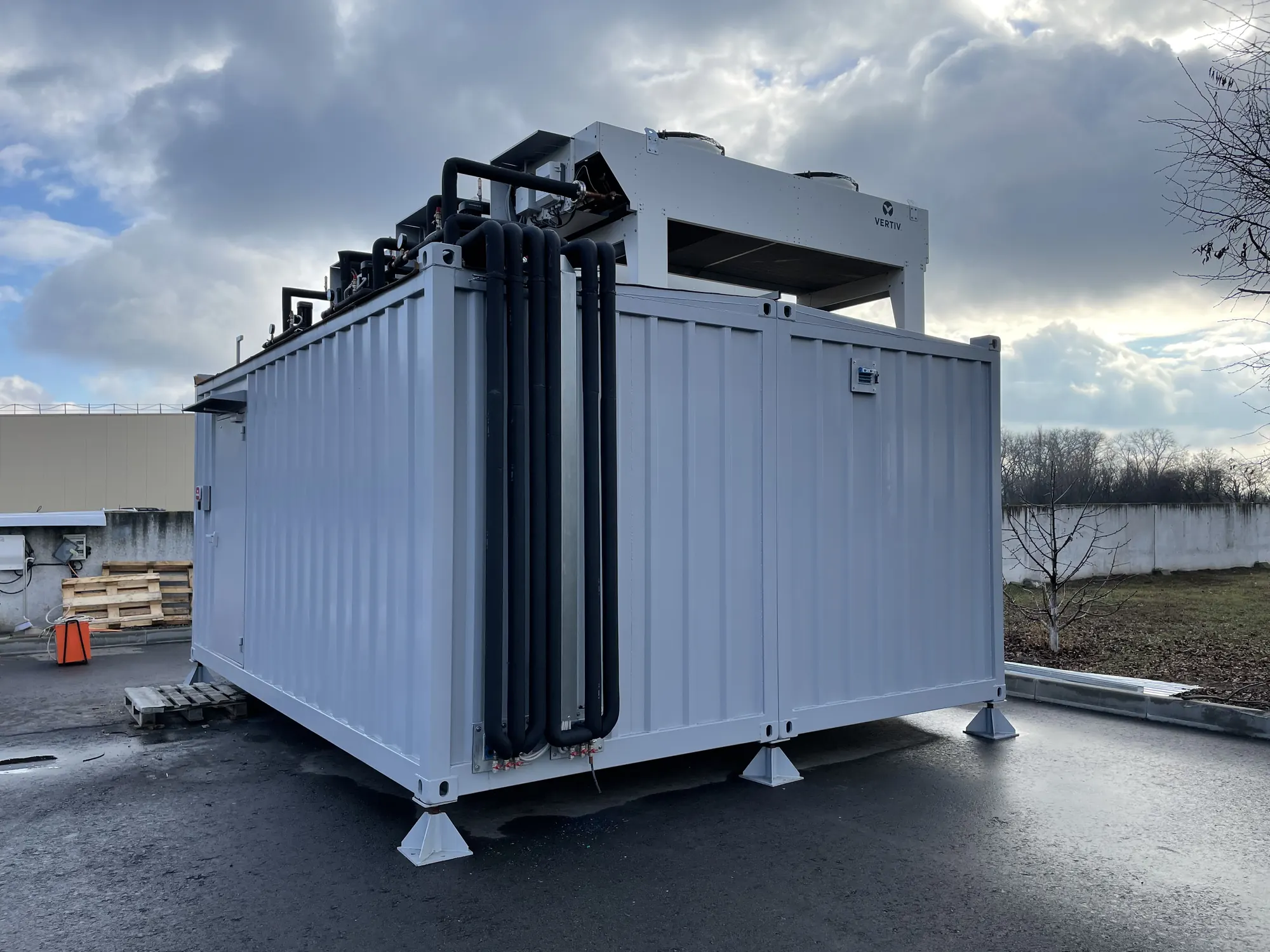
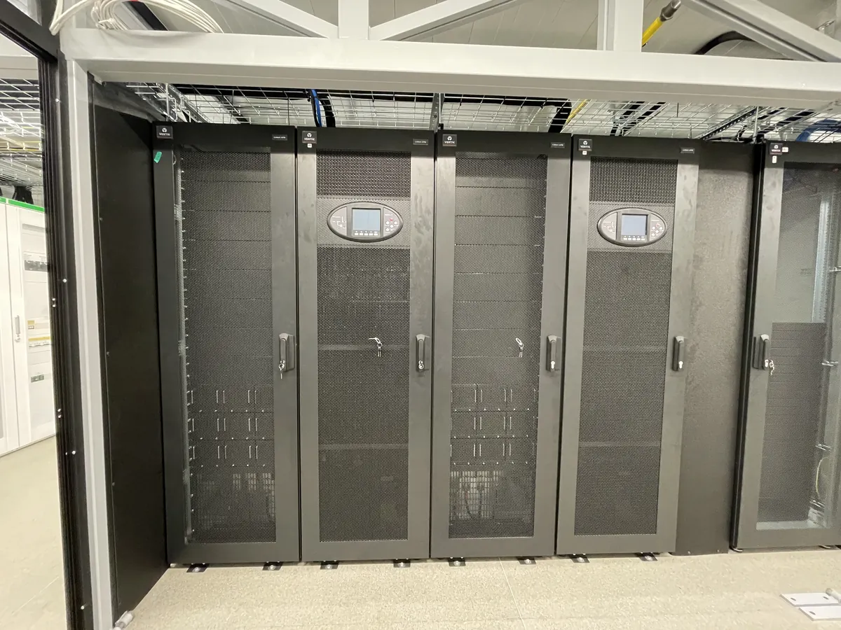
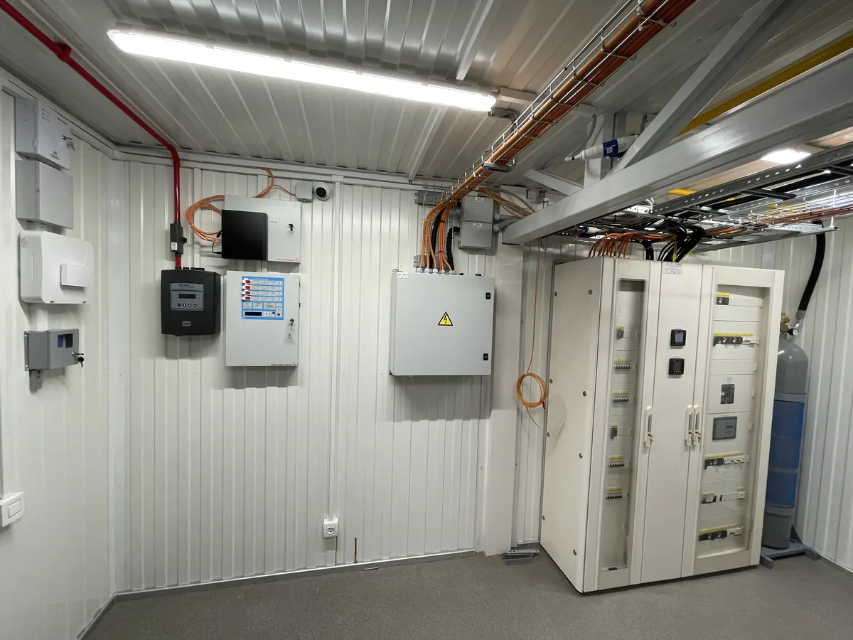
20 kW IT · 2 × 42U racks · full 2N power
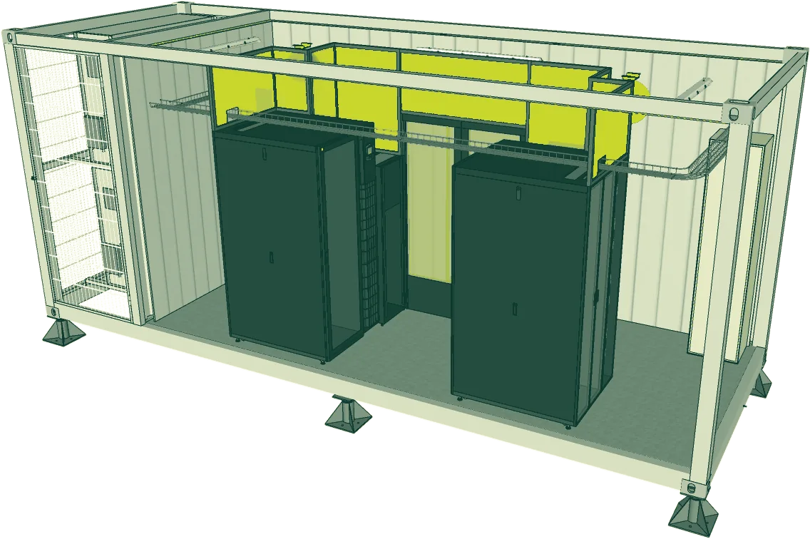
The smallest system in the range. Two independent UPS strings and dual rack distribution protect edge deployments where power-path separation matters more than expansion space. Baseline battery autonomy is 15 minutes at full IT load, sized to generator transfer or extended by request.
Cooling: in-row precision air conditioning
Best fit: compact edge nodes and critical local services
40 kW IT · 3 × 42U racks + telecom · N+1
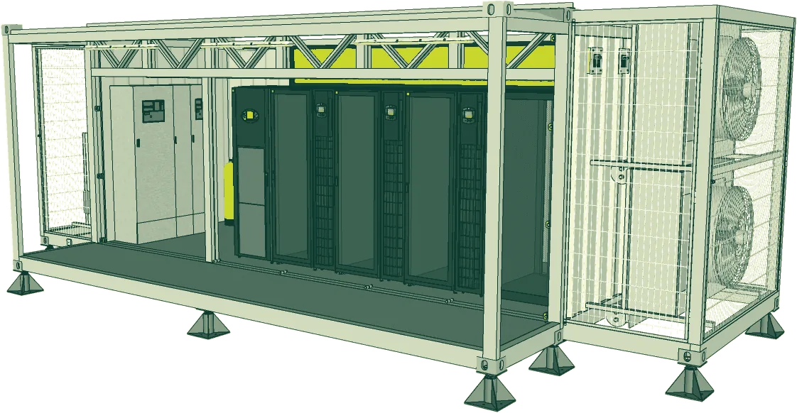
A compact branch or edge data center with a dedicated telecom cabinet, modular UPS and N+1 precision cooling. Baseline battery autonomy is 10 minutes at full IT load, with longer runtime available by project.
Cooling: precision air conditioning with N+1 units
Best fit: branch infrastructure and local application platforms
80 kW IT · 9 × 42U racks + telecom · N+1
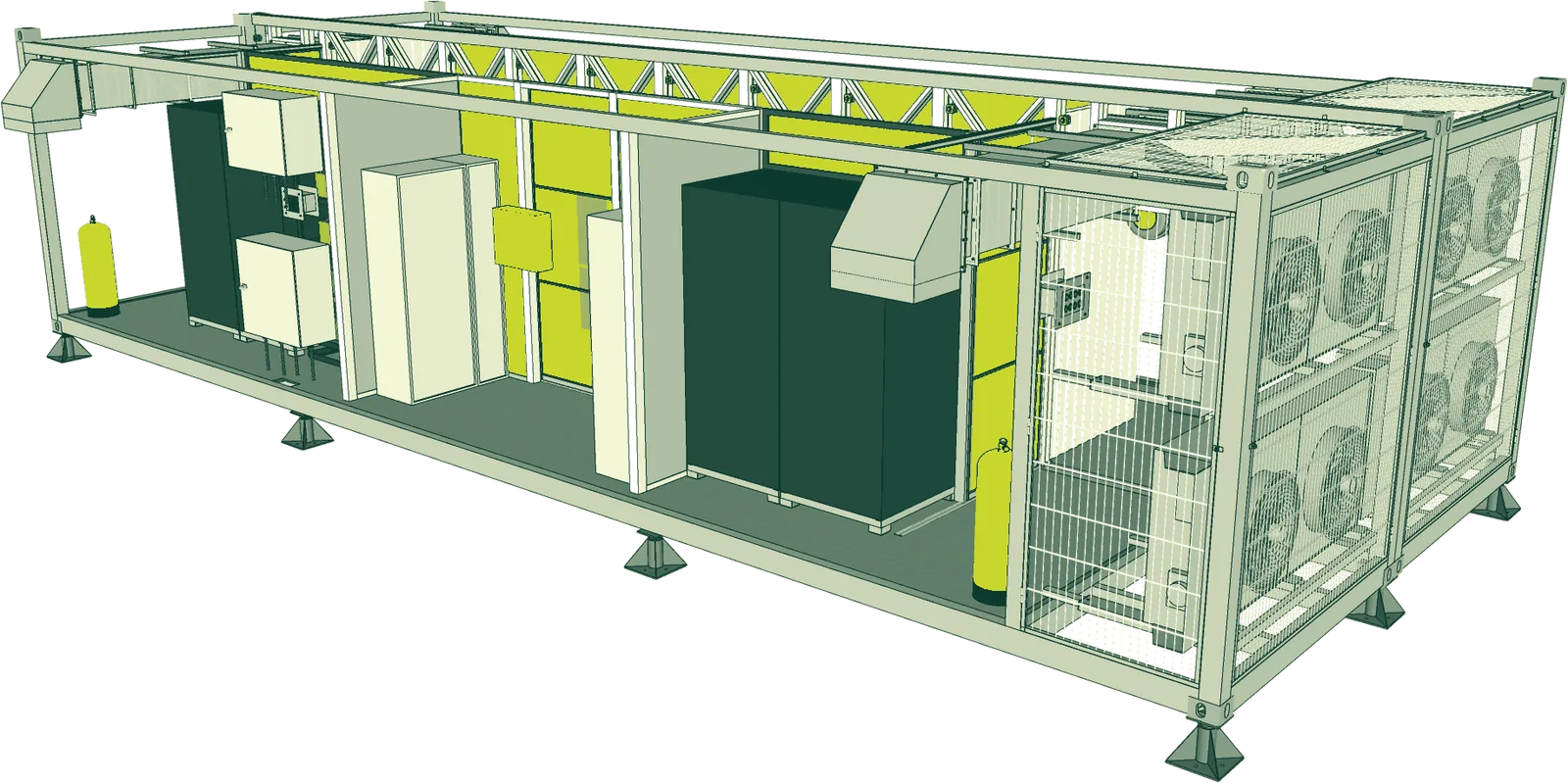
A mid-range system with a separate entrance chamber and indirect free cooling. Cabinet-mounted precision air conditioners take over when ambient conditions cannot carry the load.
Cooling: indirect free-cooling unit + N+1 cabinet precision AC
Best fit: mid-sized enterprise and regional edge capacity
120 kW IT · 14 × 42U racks + telecom · N+1
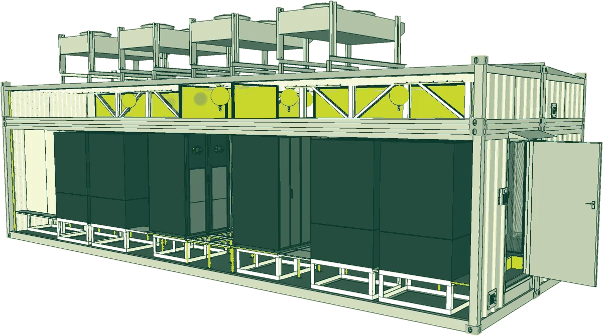
The largest integrated single-module configuration. A raised technical floor supports service distribution. Climate-suitable sites can use direct free cooling, with mechanical cooling for peak conditions.
Cooling: N+1 direct free cooling with mechanical backup
Best fit: dedicated enterprise platforms and larger on-premises estates
200 kW baseline · 20 × 42U racks + 2 telecom · N+1
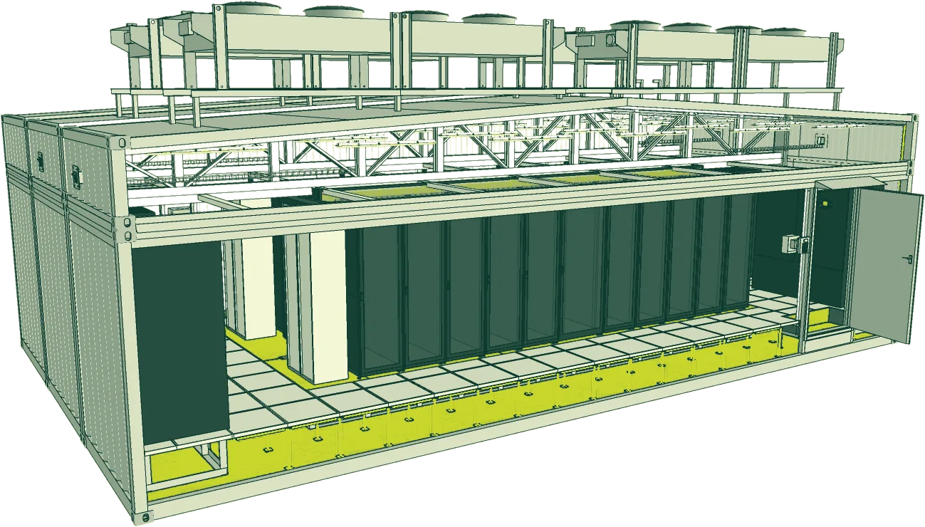
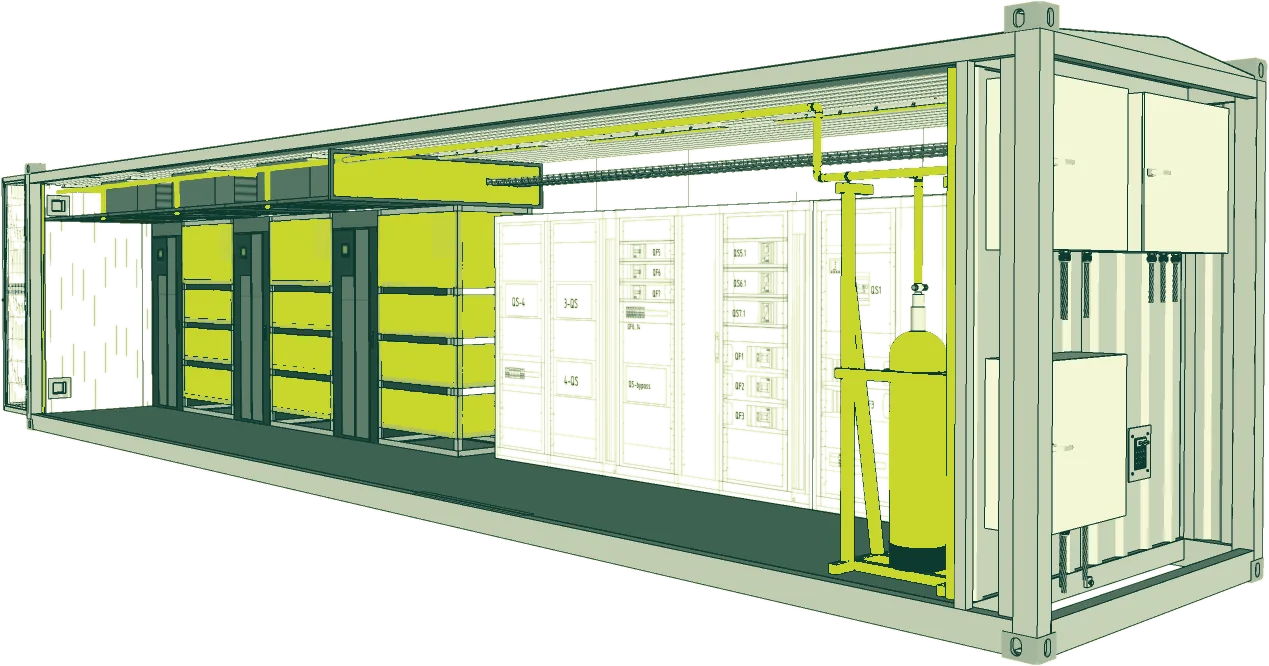
Type XL separates the IT space from a dedicated Power Module. Transformers, MV/LV switchgear, modular UPS and batteries stay in their own electrical room. A defined power-and-cooling uplift takes the platform to 264 kW.
Cooling: mechanical baseline; direct free cooling optional at suitable sites
Best fit: fixed sites that need a clear expansion path
| Model | IT load | Server racks | Telecom | Power redundancy | Cooling |
|---|---|---|---|---|---|
| Type XS | 20 kW | 2 | Optional | Full 2N | In-row precision air conditioning |
| Type S | 40 kW | 3 | 1 | N+1 | Precision air conditioning, N+1 |
| Type M | 80 kW | 9 | 1 | N+1 | Indirect free cooling + precision AC, N+1 |
| Type L | 120 kW | 14 | 1 | N+1 | Direct free cooling + mechanical backup, N+1 |
| Type XL | 200 kW baseline; up to 264 kW with uplift | 20 | 2 | N+1; dual paths available by request | Mechanical baseline; direct free cooling optional |
These issued catalog configurations retain their own ratings, rack counts and options. The broader 20–300 kW product direction does not change a Type XL rating or make 300 kW a standard upgrade.
Local capacity can serve latency, connectivity, continuity or control requirements. Select the facility around the reason the equipment needs to be there.
01
Process control, local analytics or interactive systems cannot wait for a distant region.
02
Data is generated locally, and sending all of it upstream is expensive or impractical.
03
The site must retain critical capability when external connectivity is constrained.
04
The organisation needs a defined physical, operational or data-residency boundary.
Share the applications and storage requirements so we can assess the right capacity and operating model.
Check the selected enclosure, delivery route and service clearances alongside the equipment, power and cooling requirements.
In Type XL, transformers, switchgear, UPS and batteries sit in a separate electrical room. Power-equipment heat stays outside the IT cooling path. Technicians can service the power system without entering the white space.
The 264 kW configuration is an engineered uplift, not the default Type XL rating. Cooling and Power Module capacity must be upgraded together.
Match IT load, rack count, density and resilience.
Resolve utility, cooling, network, civil, security and site access.
Integrate the agreed power, cooling, protection and control systems, then execute the defined FAT.
Connect at site, complete SAT and verify the operating system before handover.
The factory and site programmes can run in parallel. Final timing depends on the configuration, equipment availability, logistics, civil readiness and approval path.
You do not need a finished specification. The first review is where we find the missing decisions.
ModulEdge's conventional range provides local infrastructure for CPU servers, storage and networking. Typical applications include enterprise IT, edge sites and systems that need dedicated capacity close to their operations. It is an air-cooled product route, distinct from the higher-density AI configurations.
The published conventional range covers 20–300 kW of IT load, configured around the equipment and site. Rack count and maximum load per rack are selected together. Total IT capacity is separate from the site power required for cooling, electrical losses and other facility systems.
A container data center uses a defined transportable enclosure; a modular facility can also be assembled from purpose-built technical sections. The selected conventional configuration determines the enclosure, dimensions and transport method. Confirm those details from the project layout rather than assuming every model fits one shipping container.
Plan foundations, available electrical supply, fibre connections, delivery and lifting access, and space to operate and maintain the facility. Cooling equipment and service routes also need room outside the IT enclosure where specified. The issued site layout sets the loads, clearances and connection points.
Existing UPS, generator, power distribution or monitoring systems can be considered during the interface review. Share their ratings, topology, controls and operating constraints. The design must establish which equipment remains in use, what new equipment is needed and how the combined system will be tested.
Relocation and expansion can be included in the original brief. Transport dimensions, lifting points, foundations and reconnection work need to support a future move; power, cooling and fibre capacity need to support growth. These provisions are configuration-specific, rather than automatic features of every modular installation.
The main inputs are IT load, rack population, cooling duty, UPS and battery scope, redundancy, enclosure requirements and site interfaces. Civil works, upstream electrical equipment, transport and installation should be identified separately. A 20 kW edge site and a 300 kW enterprise deployment need different scope and cost assumptions.
Factory acceptance testing checks the agreed electrical, cooling, protection, monitoring and alarm functions before shipment. Site acceptance and commissioning then verify the installed facility and its utility and network interfaces. Test criteria and any required failure or maintenance scenarios belong in the acceptance plan.
[ EARLIER MODULAR DATA CENTER PROJECTS · 35–320 kW ]
120kW
Ukraine
Two joined 40-ft modules provide up to 120 kW IT load for public-sector systems, using free cooling and precision air conditioning in a relocatable facility.
Read the case study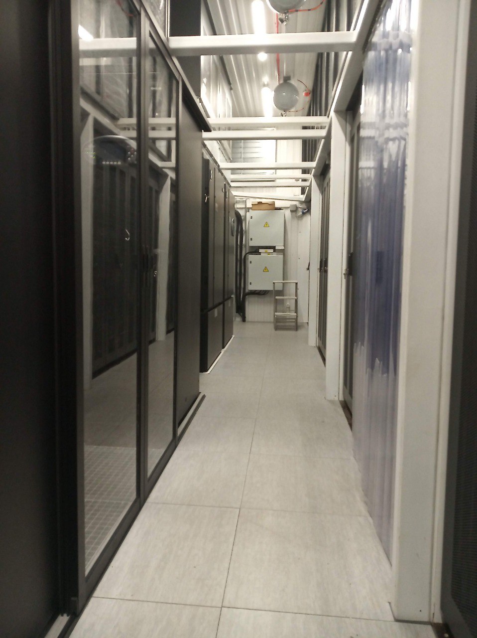
35kW
Eastern Europe
A 35 kW modular data center with indirect free cooling, built from two shortened modules to pass through a narrow archway and operate inside a historic courtyard.
Read the case study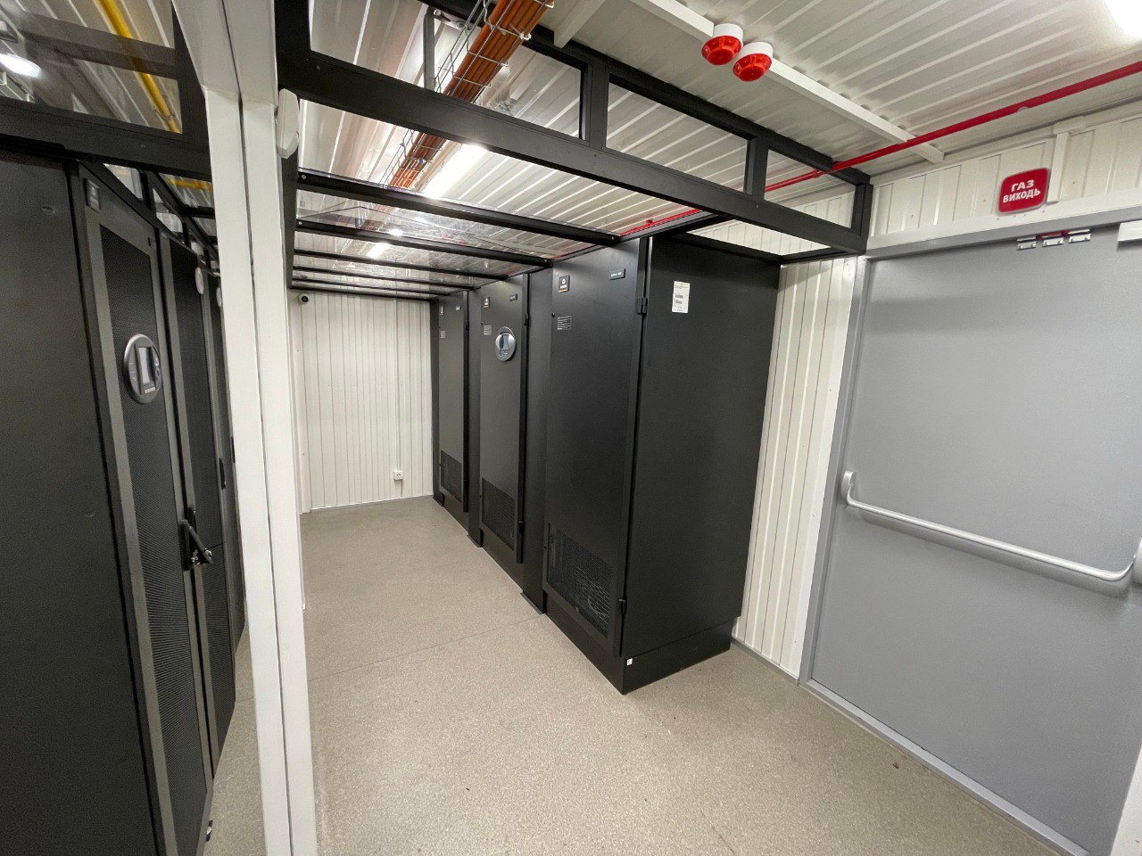
Share the CPU or storage equipment, IT load and location. We will help define the capacity and site design.